What am I fitting?
Boost gauge to monitor boost levels from the turbo charging on my engine.
Oil pressure gauge to monitor the running pressure of the engine oil.
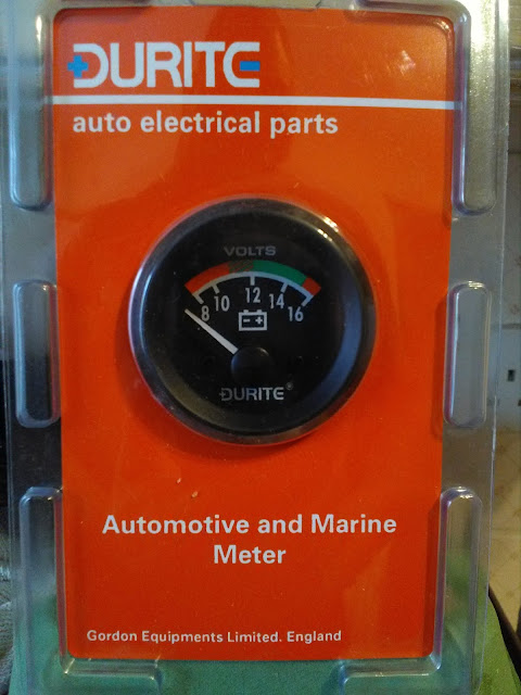
Voltmeter so I can monitor the voltage of the battery and the charge output of the alternator.
Both the voltmeter and oil pressure gauges are electrically operated and the boost gauge is a manual air line from the manifold to the gauge itself, many people take their pressure readings from the boost pipe that operates the boost fuelling diaphragm on the injection pump, I don't like that method as it delays fuelling and there is always a drop in pressure from the turbo to the manifold and I prefer to take my measurement from the manifold as it shows the absolute pressure after losses from intercooler expansion etc,.
To begin I remove the inlet manifold from the engine so I can drill and tap it to accept the barbed union for the feed line.
Unbolt dipstick tube.
Then the 8 bolts holding the manifold to the head.
A special 11/32 HSS twist drill was purchased for the job as many hydraulic type unions still use imperial threads and the barbed union was no different.
Here is the barbed union fitted post drilling and tapping, this was fitted with a few drops of thread seal to ensure that the fitting is 100% air tight.
So I picked a spot on the dash to mount the dash pod and now need to get the dash drilled and the wiring through from beneath the dash to the gauges. A short length of spare cunifer brake pipe and a few wraps of tape help get them through the mass of wiring and air vent pipes under the dash.
Here you can see the wires and pipe pulled up through the dash and you can see the cable ducting that I have used to both separate and protect this particular loom from the rest.
The bundle contains the +ve from the fuse box, signal wire from the oil pressure gauge and the pressure pipe from the manifold.
The gauges do still require a -ve which was taken locally from the dash board support frame and a +ve feed from the dash lamps to illuminate them when I turn the lights on, again this was sourced locally from the instrument cluster lighting.
Sadly I didn't get a picture of the plug that I used to wire these up to make the pod easily removed from the dash without having to try and undo individual wires from the back of individual gauges.
This is the cabling in the ducting being routed through the grommet I fitted in the pedal panel under the dash taking the loom through to the engine bay.
Boost pipe was warmed in my cup of tea and quickly slipped up the barbs and secured with a crimp to ensure it's air tight.
Using more cable ducting to keep this loom separate I routed it up and over the engine to where the fuse box and the mounting point for the oil pressure sender.
In order to fit the pressure gauge you have to either sacrifice the warning lamp sender or fit a "T" piece that will enable you to keep the lamp sender and fit the pressure gauge sender.
The oil filter housing sits quite low on a 200Tdi engine and I was nervous about the vulnerability of the "T" piece and opted to fit it as a remote unit on a custom braided stainless oil feed line.
I then had to come up with a means of mounting it all to the bulkhead and found a "U" clamp combined with a stout galvanised angle iron bracket to be just the right solution.
You can see the shiny stainless pipe where it is fitted into the oil filter housing.
And the finished articles are up and running.
Get her done and please, like, share and comment.


No comments:
Post a Comment